Flow battery solar container technology schematic diagram
DOE ESHB Chapter 6 Redox Flow Batteries
Figure 1 is a schematic of a typical, single cell flow battery used for research and development. Here the catholyte (green) is housed in the tank on the left, while the anolyte (blue) is housed in the tank on

DOE ESHB Chapter 6 Redox Flow Batteries
One tank of the flow battery houses the cathode (catholyte or posolyte), while the other tank houses the anode (anolyte or negolyte). Figure 1 is a schematic of a typical, single cell flow battery used for

Advancing grid integration with redox flow batteries: an engineering
The widespread use of fossil fuels, along with rising environmental pollution, has underlined the critical need for effective energy storage technologies. Redox flow batteries (RFBs) have emerged a...

Electrical schematic diagram of energy storage system
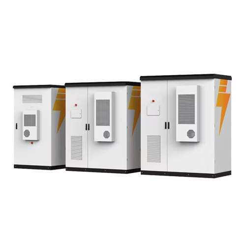
A battery energy storage system is of three main parts; batteries, inverter-based power conversion system (PCS) and a Control unit called battery management system (BMS). Figure 1 below presents
Schematic diagram of a battery storage system connected with the
Download scientific diagram | Schematic diagram of a battery storage system connected with the grid. from publication: Saviztky-Golay Filtering for Solar Power Smoothing and Ramp Rate Reduction
Schematic diagram of photovoltaic energy storage battery structure
This diagram serves as a visual guide in understanding the functionality of each component and how they work together to provide clean and renewable energy for various applications.
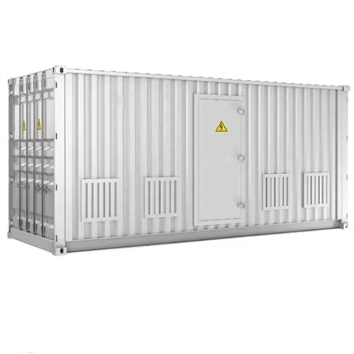
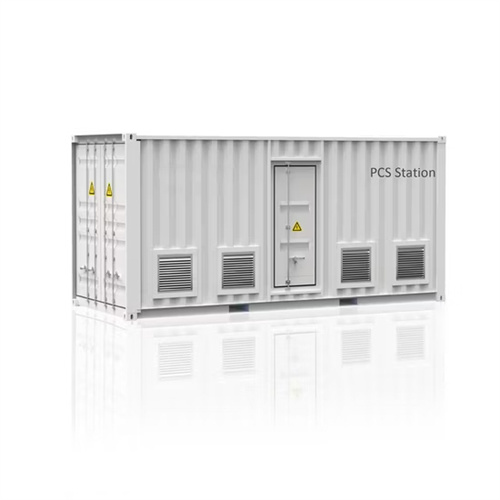
Utility-scale battery energy storage system (BESS)
Utility-scale BESS system description — Figure 2. Main circuit of a BESS Battery storage systems are emerging as one of the potential solutions to increase power system flexibility in the presence of
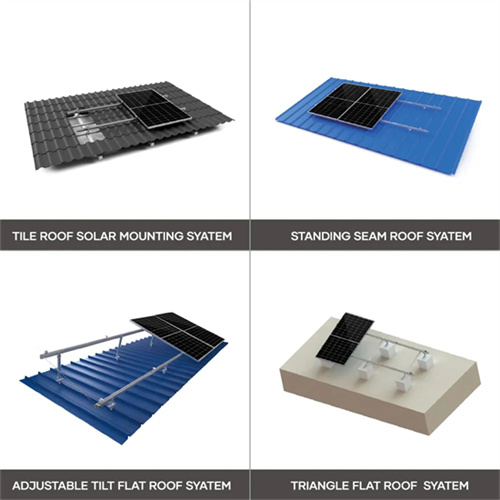
The Ultimate Guide to Understanding Pv System Diagrams
Learn about the PV system diagram and how solar panels convert sunlight into electricity. Understand the components involved in a solar photovoltaic system and how they work together to generate
Flow battery energy storage system drawings
A flow battery is a form of rechargeable battery in which electrolyte containing one or more dissolved electro-active species flows through an electrochemical cell that converts chemical energy directly to
Rechargeable redox flow batteries: Flow fields, stacks and design
ref. 10. Figure 2 (a) Schematic of a typical flow battery and (b) A detailedBdiagram of cell compartment in flow batteries with a flow field design, main components include: 1Bendplates, 2Bcurrent collectors,
Schematic diagram of a flow battery system.
Polymer electro- lyte fuel cells and flow batteries share many design features and materials of construction. Fuel cells generally contain precious metal catalysts that are absent in flow batteries,
Related Contents
- Ranking of experts in flow battery solar container technology
- Schematic diagram of aluminum iron phosphate solar container battery
- Liquid flow battery solar container technology project introduction
- Schematic diagram of sodium ion battery solar container principle
- Schematic diagram of high voltage box for solar container lithium battery
- New solar container technology iron-chromium flow battery
- Pros and cons of flow battery solar container technology
- Manganese iron liquid flow battery solar container principle diagram
- Schematic diagram of industrial solar container backup battery principle
- Schematic diagram of solar container battery
- All-vanadium liquid flow battery solar container technology is awesome
- Schematic diagram of a large battery solar container power station