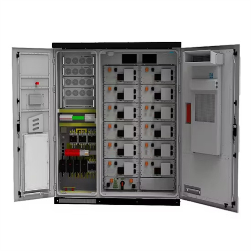
Design schematic diagram of microgrid solar container inverter
Phase Locked Loop Control of Inverters in a Microgrid
The proposed control strategy is based on the use of a phase locked loop to measure the microgrid frequency at the inverter terminals, and to facilitate regulation of the in-verter phase relative to the
Design and Implementation of a Microgrid-Capable Solar Inverter
1.1 Microgrid Layout The microgrid used in this project is a set of three hardware-simulated generators and six basic loads, intended to model a typical commercial load that would be connected to the grid.
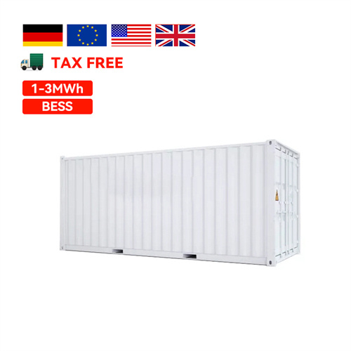
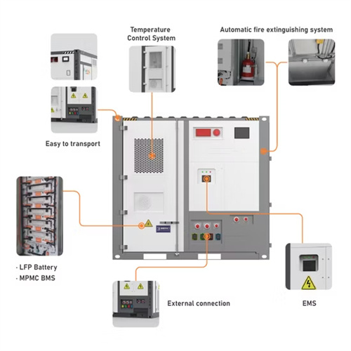
Utility-scale battery energy storage system (BESS)
Grid Forming Inverter – Proven grid forming inverter with flexible operating mode, allowing microgrid application in remote or islanded grids. Flexible on-grid/off-grid operation – flexible functional state
Schematic diagram of a Microgrid. | Download Scientific Diagram
Download scientific diagram | Schematic diagram of a Microgrid. from publication: Embracing Microgrids: Applications for Rural and Urban India | This article details the possibilities on the
Integrated Synchronization Control of Grid-Forming Inverters for
Abstract This paper develops an integrated synchronization control technique for a grid-forming inverter operating within a microgrid that can improve the microgrid''s transients during microgrid transition

Design and Implementation of a Microgrid-Capable Solar Inverter
Abstract ies are installed more frequently in areas lacking a pre-existing central grid. To research the effects of both intentional disconnects and unintentional faults within a microgrid and between it and
Related Contents
- Inverter solar container power supply circuit schematic diagram
- Schematic diagram of inverter solar container device
- Bidirectional inverter solar container power supply schematic diagram
- Detailed picture of solar container inverter schematic diagram
- Schematic diagram of inverter plus solar container battery
- Photovoltaic off-grid solar container system design diagram
- Schematic diagram of sodium ion battery solar container principle
- Smart solar container operation process design diagram
- Solar container battery design assembly diagram
- Schematic diagram of gas solar container electromagnetic catapult
- Solar container inverter parameter diagram
- Distributed photovoltaic solar container microgrid design