Schematic diagram of mobile solar container conversion circuit
Mppt Solar Inverter Circuit Design
Mppt Solar Inverter Circuit DesignIt''s no secret the world is looking for sustainable energy solutions with solar being one of the top contenders due

Solar Powered Mobile Charger Circuit
To convert solar energy into electricity, we will need solar panels. Here we design a solar mobile phone charger circuit to charge our mobile phone
Solar Cell Circuit Diagram
A solar cell circuit diagram is a blueprint for an electrical system that utilizes solar cells to generate electricity. In today''s world, these circuits can
Working Principle of DC-DC Conversion Circuit in MPPT
Internal circuit schematic diagram of single-phase inverter The figure listed above presents a topological structure commonly used by single
Simple Off-Grid Solar Wiring Diagram
This schematic visual representation will show you exactly how everything in our Victron based 3kW, 5kWH, 120V off-grid battery and solar system connects
How to Design a Solar Inverter Circuit
When a DC to AC inverter is operated through a solar panel, it is called a solar inverter. The solar panel power is either directly used for operating

Solar Panel Array Schematic » Wiring Diagram
The term ''solar panel array schematic'' refers to the wiring diagram of a photovoltaic (PV) system, which details the way in which components are connected. Typically, it includes the
Real MPPT Solar Charger Circuit Using Arduino, LCD, and
Arduino Nano (or UNO) Solar Panel (18V, 50W or similar) Buck Converter circuit with N-channel MOSFET and diode Current sensor (ACS712 or INA219) 16x2 LCD Display 10k pot for
Circuit Diagram For Solar Mobile Phone Chargers
A normal circuit diagram has several components, including an inverter, diodes, resistors, capacitors, and transistors. With these components,

Solar Powered Mobile Phone Battery Charger
This is the schematic diagram of solar powered mobile phone battery charger. The circuit is designed to charge the battery from a source with a lower voltage. Do not use it to charge the battery with the
Circuit diagram of solar energy conversion system
Solar enerji ile üretilen elektrik enerjisinde solar radyasyon kullanılarak bu tezin de konusu olan fotovoltaik yani solar hücrelerle elektrik enerjisi üretim yöntemi yer

Make this Solar Charger Circuit with Auto Cut-Off Using
Thats it! This is how we make a simple but effective solar battery charger with automatic cut-off, using just transistors and zener diodes, no

Circuit: DIY Solar Panel Voltage Converter | Elektor
Would you like a compact power supply for small indoor IoT devices? With this DIY solar panel voltage converter project, which was
BESS Methodology
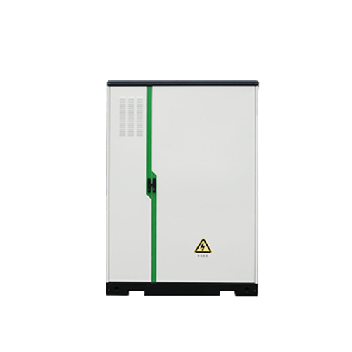
The dimensions of the battery containers and the power conversion system will be determined by the user. In order to keep the same pvDesign philosophy with the power station dimensions of the PV
Solar Panel Wiring Diagram Example – Wiring Flow
Solar panel wiring diagrams can be quite complex, but with some practice and patience, they can be mastered. With the help of this example diagram, you can
Schematic of power conversion circuit of front-end
Download scientific diagram | Schematic of power conversion circuit of front-end Boost converter of solar UAV In Figure 8, USA and ISA are solar array voltage
Circuit Diagram of a Solar Cell | Download Scientific
The simplest equivalent circuit of a solar cell is a current source in parallel with a diode, shown in Fig. 2 [30]. The series resistance R S represents the internal
Solar Circuit Diagram
A solar circuit diagram is a visual representation of the electrical components used in a solar energy system. It shows how the different pieces fit together to create the desired output.
1: Circuit diagram (mobile phone connects with solar
In this paper, solar fed single-input two-output Converter is discussed in the application of low power. The single-diode model is chosen for the solar panel
Solar Power Mobile Charger Circuit
And, for this reason, we have decided that, in this tutorial, we are going to "Solar power mobile charger circuit ". A solar charger circuit is a device
Solar Power Mobile Charger Using Buck Converter
For that purpose designed an eco-friendly solar powered charger (SPC) for mobile charging which utilizes an effective converter topology and microcontroller to ensure effective utilization of solar energy.

6 FAQs about [Schematic diagram of mobile solar container conversion circuit]
What is solar power mobile charger circuit?
And, for this reason, we have decided that, in this tutorial, we are going to “Solar power mobile charger circuit “. A solar charger circuit is a device that generates power from sunlight. Cell phones, computers, automobile batteries, reading lamps, and personal fans all can use this power to charge their equipment.
How a solar power mobile charger works?
1. 2. 3. 4. 5. 6. 7. The Solar power mobile charger circuit uses a solar panel with a single PN junction diode 1N4007 connected to the solar panel’s positive line to prevent reverse polarity. After the capacitor C1, a green LED is connected across the solar panel supply line to show the condition of the solar panel’s supply output.
Is a mobile charge a part of an MPPT solar charge controller?
A mobile charge was not so important as part of an MPPT solar charge controller, but was kept in the design to make the project more useful and interesting. Here, a Switch Mode Power Supply circuit is designed with the MC34063A IC, which can supply 5V at 350mA very easily. The circuit diagram for our mobile charger is:
How does a Zener diode work?
The Zener diode is reverse biassed and linked at the base of the SL100 transistor. When the sunlight strikes the solar panel, the photovoltaic device which is a solar panel cell converts the solar energy into voltage, and the green LED shines. The intensity of the LED fluctuates depending on the voltage generated by the solar panel.
What is a PV module?
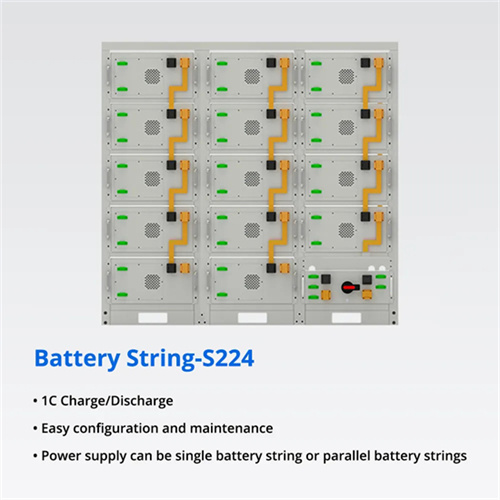
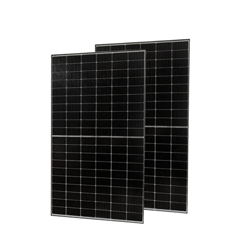
A PV module is an assembly of photovoltaic (solar) cells mounted in a protective framework for installation. These cells capture sunlight and convert it into direct current (DC) electricity. When multiple PV modules are grouped together, they form a PV panel, and a collection of panels is known as a solar array.
What voltage regulator IC is used in the MPPT solar charge controller?
This power supply is designed with an LM7805 voltage regulator IC. The circuit diagram is: Although most of the MPPT solar charge controllers don’t have a load control unit, in our project we kept this part. Loads are supplied from our battery and switched by a MOSFET.
Related Contents
- Inverter solar container power supply circuit schematic diagram
- Mobile solar container mechanical schematic diagram
- Mobile solar container system topology diagram
- Mobile solar container principle power station diagram
- Mobile solar container power supply circuit architecture
- Mobile solar container conversion efficiency calculation formula
- Schematic diagram of giant solar container capacitor
- Solar container system circuit diagram
- Schematic diagram of outdoor dc solar container power supply
- Schematic diagram of a large battery solar container power station
- Schematic diagram of solar container industrial liquid cooler
- Schematic diagram of solar container battery