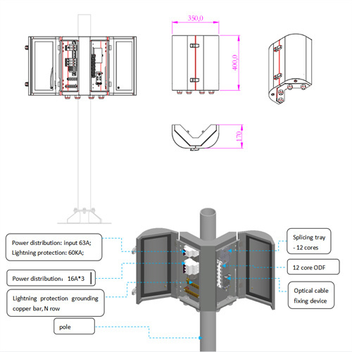
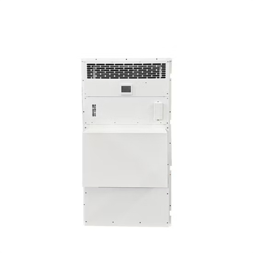
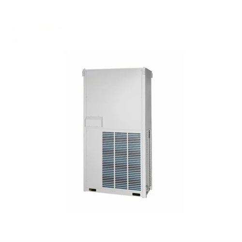
Schematic diagram of solar container industrial liquid cooler
Solar Cooling | SpringerLink
Solar energy-based absorption coolers can operate in two ways: (i) the use of continuous coolers having the same construction and operation as conventional gas or steam-fired
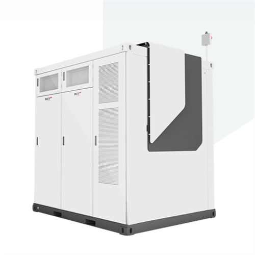
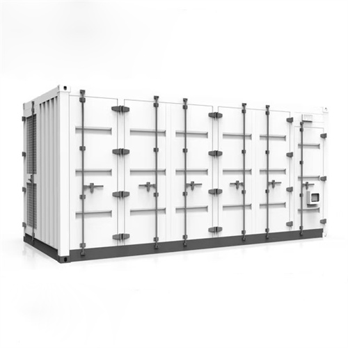
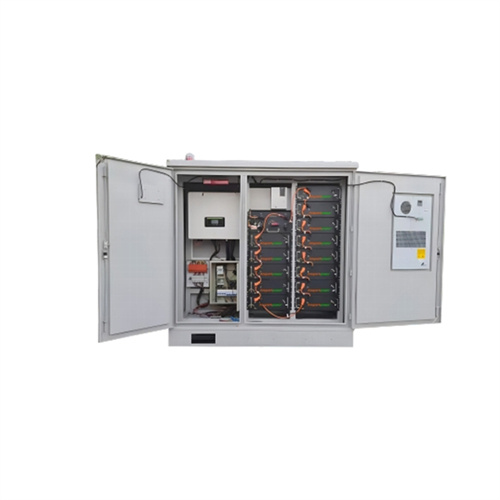
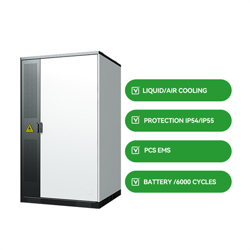
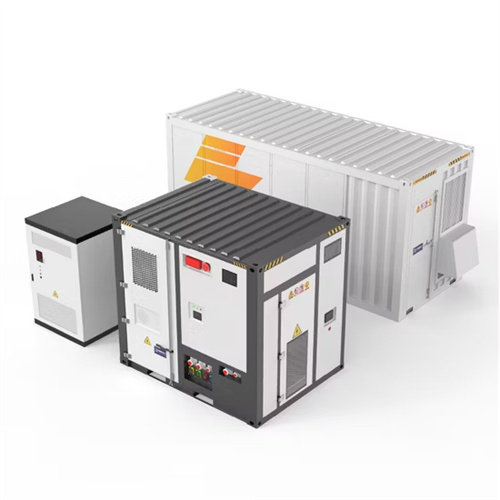
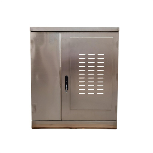
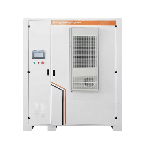
Liquid Cooling Container Energy Storage System Design Drawings
Design of Liquid Cooling Container Energy Storage System. The liquid cooling energy storage system maximizes the energy density, and has more advantag.
Schematic of a Forced-circulation solar liquid heater
Download scientific diagram | Schematic of a Forced-circulation solar liquid heater from publication: A radiant air-conditioning system using solar-driven liquid
Schematic of Solar -Operated Liquid Desiccant
Figure 1 shows the schematic of the solar-driven liquid desiccant evaporative cooling system used to serve as an open cycle absorption system operating with
Schematic diagram of an active water/water cooler in
Schematic diagram of an active water/water cooler in the solar primary loop. The approach is done by the inefficient collector operation to limit the heat generation
Solar Cold Rooms Technical Handbook
Rooms Technical Handbook comes in. It is structured in such a way that it is easily accessible even to those readers w. o are new to each technical aspect. The most important topics relevant to the
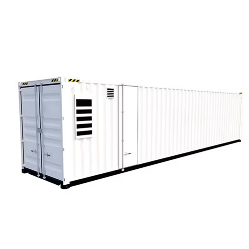
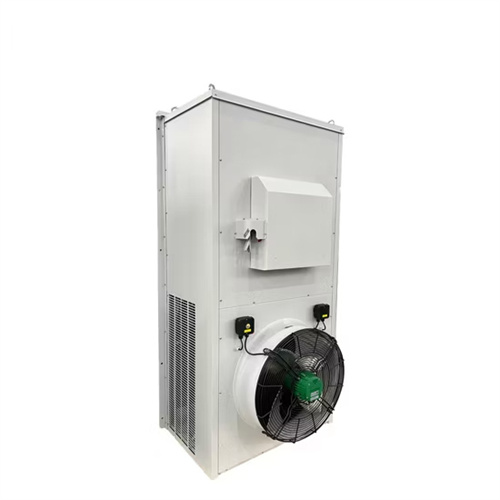
Schematic diagram of liquid cooling energy storage system
Liquid cooling BTMS improvement The optimization methods for liquid cooling BTMS can be divided into three categories: coolant,system structure,and improvement of liquid cooling-based hybrid systems.
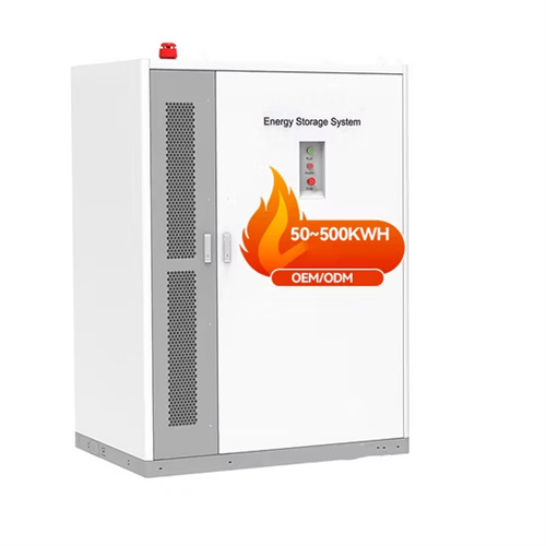
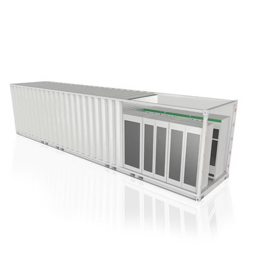
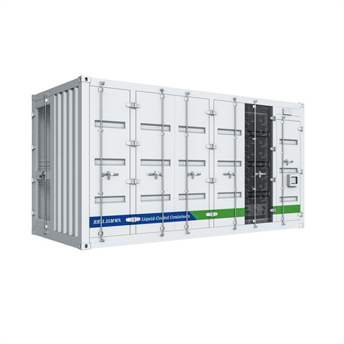
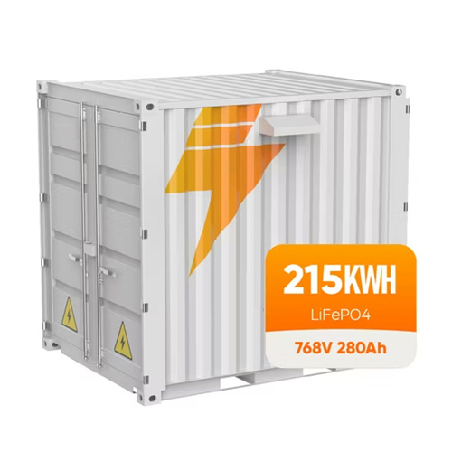
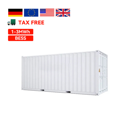
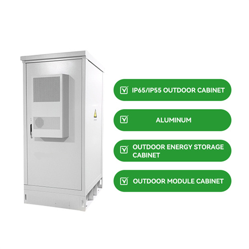
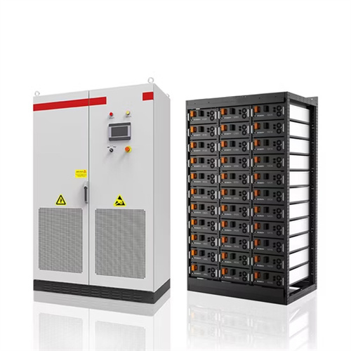
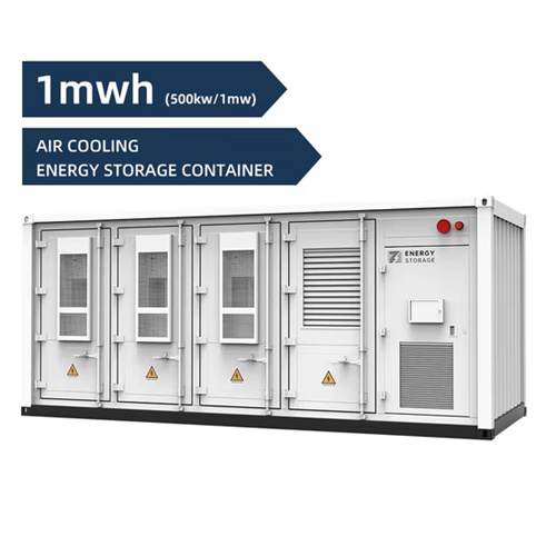
Liquid cooling Lithium Ion Baterias Container ESS
Liquid-cooled containerized energy storage is a type of energy storage system typically used to store electrical energy or other forms of energy for backup
Schematic of the solar assisted liquid desiccant system with
Fig. 1. Schematic of a desiccant cooling air conditioning [8]. Fig. 2. Moisture removal process by desiccant [6]. Fig. 3. Schematic diagram of solar air pre-treatment collector/regenerator [15]. Fig. 4.
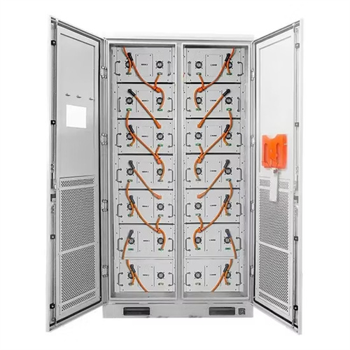
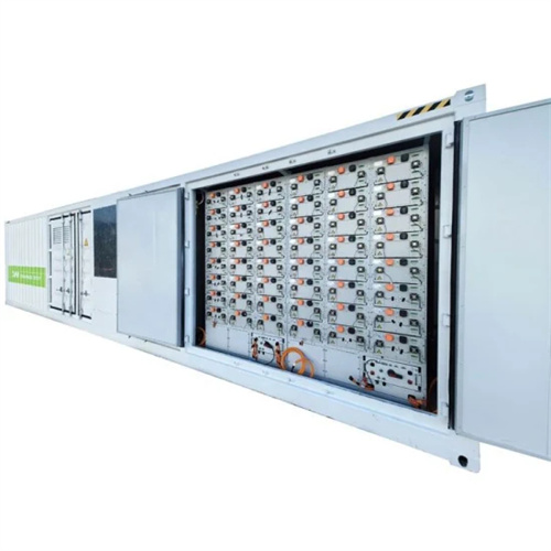
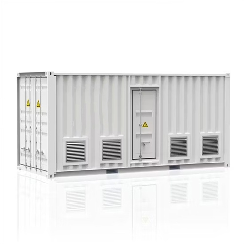
A SCHEMATIC OF LIQUID COOLING SYSTEM MODULE
The containerized liquid cooling energy storage system combines containerized energy storage with liquid cooling technology, achieving the perfect integration of efficient storage and cooling. [pdf]
e Schematic diagram of the solar desiccant assisted
Download scientific diagram | e Schematic diagram of the solar desiccant assisted distributed fan-pad ventilated greenhouse system. from publication: Greenhouse
5 Schematic diagram of the new solar refrigerator
5 Schematic diagram of the new solar refrigerator model, developed at AIT by Exell, using Activated carbon -methanol pair. (Sumathy,Zhongfu,1999,P.705)
Schematic figure of the developed solar PV air cooler
The article describes the design-development and experimental studies of a solar PV based evaporative air cooler. The solar air cooler has been designed with a
Schematic diagram of the thermoelectric air cooler
The thermal cooling enhancement technique of dual processors workstation computer couple thermoelectric air cooler module is studied experimentally. The
Schematic block diagram of an innovative experimental analysis of
Schematic block diagram of an innovative experimental analysis of optimised solar-powered Peltier-based air cooler and warmer in medical systems.
Review on the structural design of solar-driven interfacial evaporation
(f) Schematic diagram of the carbon nanotube-geopolymer composite-based salt resistance arched solar-driven evaporator. (g) The digital photographs of the change process of 0.3 g
Schematic diagram of the solar cooler.
Download scientific diagram | Schematic diagram of the solar cooler. from publication: Performance of a fabricated solar-powered vapour compression
Schematic of the liquid cooling design.
Download scientific diagram | Schematic of the liquid cooling design. from publication: Cooling Systems in Data Centers: State of Art and Emerging
Schematic diagram of an absorption cooling system
Download scientific diagram | Schematic diagram of an absorption cooling system activated with solar energy. from publication: Optimum operational strategies for
Schematic diagram of solar operated combined
Solar energy is utilized in a combined ejector refrigeration system with an organic Rankine cycle (ORC) to produce a cooling effect and generate electrical power.
Design and performance analysis of portable solar powered cooler for
The solar ‐powered cooler presents an innovative method to address the challenges of remote locations and unreliable power supplies in most remote areas. This innovative approach is particularly valued
Schematic representation of a solar assisted liquid
Download scientific diagram | Schematic representation of a solar assisted liquid desiccant system with evaporative pad from publication: Protected Cropping in
Schematic diagram of solar powered desiccant
The extensive effort has made to fabricate and analyze the evaporative cooler with liquid-desiccant regeneration process. A temperature drop of around 4 degrees
Recent developments in solar assisted liquid desiccant evaporative
A basic description of the principles of hybrid solar liquid desiccant with direct and indirect evaporative cooling is provided. Finally, solar regeneration methods and recent developments
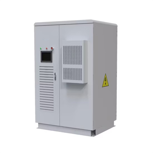
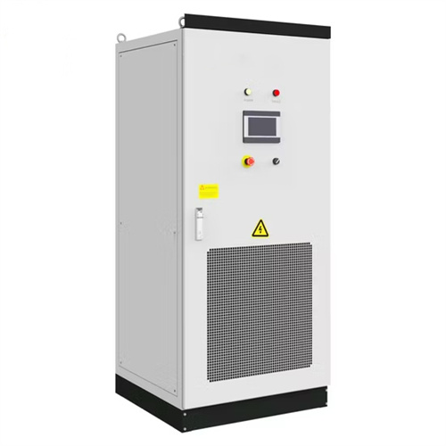
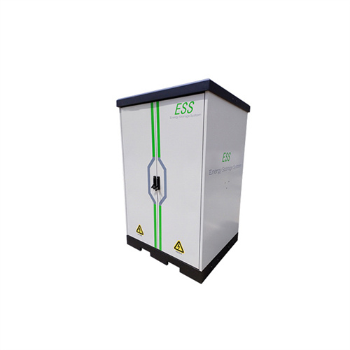
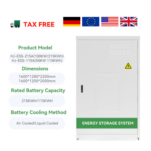
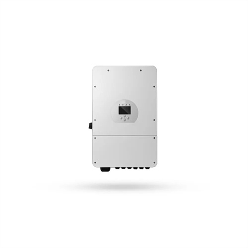
125kW 261kWh Liquid Cooling All-in-one Industri...
Featuring an advanced liquid cooling system, integrated 125kW PCS, and high-density 314Ah lithium batteries, this AC-coupled solution is engineered for large-scale commercial, industrial, and utility
Schematic diagram of the refrigeration system.
Download scientific diagram | Schematic diagram of the refrigeration system. from publication: Performance prediction of a solar refrigeration system under various
Solar Panel Wiring Diagram for All Setups [+ PDFs] –
With any solar DIY project, you need to know how your components connect. Read on to learn how to create a solar panel wiring
Schematic of an evaporative cooler. | Download
Download scientific diagram | Schematic of an evaporative cooler. from publication: Cooling of Greenhouses using Seawater: a solar-driven liquid desiccant cycle for
Schematic of the solar assisted liquid desiccant system with
Schematic diagram of the solar LDAC system [6,29]. systems coupled with direct and indirect evaporative coolers. A numerical model was developed in the simulation environment TRNSYS and
Schematic of Solar-Operated Liquid Desiccant
Figure 1 shows the schematic of the solar-driven liquid desiccant evaporative cooling system used to serve as an open cycle absorption system operating with
Schematic diagram of an active water/air cooler in the
Download scientific diagram | Schematic diagram of an active water/air cooler in the solar primary loop. from publication: Overheating prevention and stagnation
Schematic of the liquid desiccant space cooling system
Download scientific diagram | Schematic of the liquid desiccant space cooling system [44]. from publication: Historical review of liquid desiccant evaporation
6 FAQs about [Schematic diagram of solar container industrial liquid cooler]
What is solar cooling?
ning tags12 SOLAR POWERED COOLINGThe term Solar cooling involves a number of different technologies which can be generally classified by the form of their energy source. Solar cooling by sorption (absorption and adsorption) is using Solar th
How does solar powered cooling work?
ered Cold Rooms and Refrigeration". Solar powered cooling uses PV generated DC current which can be either converted by an inverter into alternating current (AC) to dr ve a regular AC cooling compressor. For the second option the DC power is used directly to drive a series of small DC compressors with an additional l
What are the problems of a sole PV/battery cooling system?
Solar Cooling with Latent EnthalpyAnother major problem of a sole PV/battery cooling system is shown in Fig. 84. With increasing Solar radiation in the morning hours, an adequately sized PV generator will provide enough power for product co ling and to recharge the batteries. Around midday the batteries should be
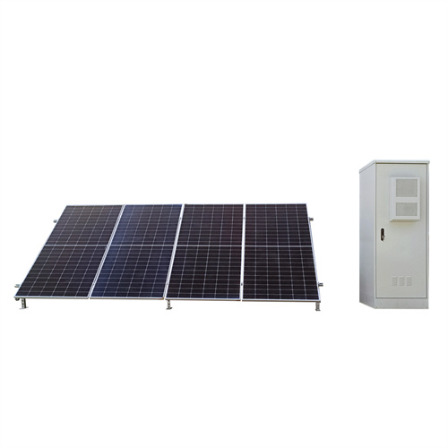
How do solar panels cool a cold room?
a temperature near freezing point. Cooling for the cold room is provided by an impeller pump (D1) that pumps the cold tank water via a flexible hose to the h at exchanger unit in the cold room.Solar power c mes from three separate PV strings. Each string consists of two 380Wp panels connected in series. (2x42V OC) an has
What is solar cooling by sorption?
by the form of their energy source. Solar cooling by sorption (absorption and adsorption) is using Solar th rmal energy as its energy resource. A detailled description on this technology can be found in the transcript "Solar Po
How much ice can a PV panel produce?
e a lathent enthalpy cooling systemWith the average efficiency of a PV panel (~17%) and the real COP for cooling (200% i.e. 1 unit of electricity gen-erates 2 units of ice, one square metre of PV can produce 18kg of ice, which can be used to cool down 100kg of product
Related Contents
- Solar container liquid cooler installation diagram
- Schematic diagram of industrial solar container backup battery principle
- Industrial solar container equipment composition diagram
- Schematic diagram of a large battery solar container power station
- Schematic diagram of solar container battery
- Schematic diagram of inverter plus solar container battery
- Schematic diagram of the principle of lithium absorption in solar container batteries
- Schematic diagram of solar container unit
- Schematic diagram of power grid frequency regulation of solar container system
- Schematic diagram of mobile solar container conversion circuit
- Schematic diagram of hybrid solar container
- Schematic diagram of giant solar container capacitor