Mobile battery solar container circuit diagram explanation

Solar Power Mobile Charger Circuit
Circuit Diagram Working Explanation As we can see in the circuit, it consists of a 6V/500 mW solar panel. Here a single PN junction diode 1N4007 is connected to

1: Circuit diagram (mobile phone connects with solar
1: Circuit diagram (mobile phone connects with solar panel) Fig. shows that, a solar panel is connected with IC 7805. This integrated circuit (IC) is divided with 3

Solar Powered Mobile Charger Circuit
To convert solar energy into electricity, we will need solar panels. Here we design a solar mobile phone charger circuit to charge our mobile phone

Free Solar Inverter Circuit Diagrams
Free Solar Inverter Circuit DiagramsWith the current drive towards sustainable energy, free solar inverter circuit diagrams are a crucial resource for
Circuit Diagram Of Solar Battery Charger For Mobile
It illustrates the components of the device, such as the solar cells, the rechargeable battery, and the connectors for the device, as well as the wiring

PV Solar Inverter Circuit Diagram
The output voltage from the solar panel is immediately supplied into the LM317 positive regulator circuit, which is regulated to produce 12 volts. The battery is
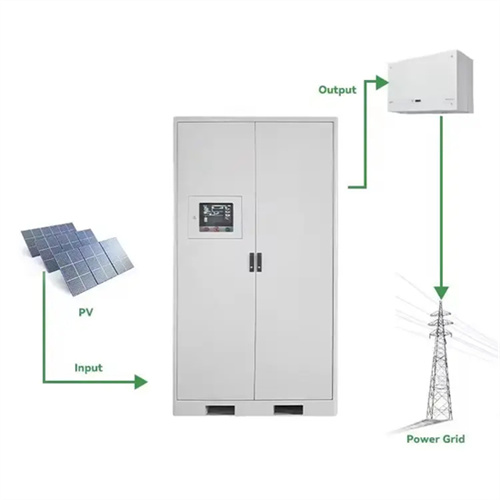
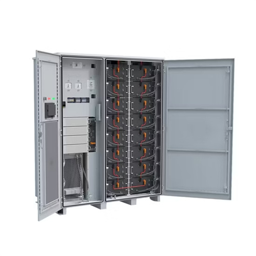
Utility-scale battery energy storage system (BESS)
Utility-scale BESS system description — Figure 2. Main circuit of a BESS Battery storage systems are emerging as one of the potential solutions to increase power system flexibility in the presence of
Solar Battery Charger Circuit | PDF | Battery Charger
This document describes a simple circuit to charge a 12V lead-acid battery using a 5W solar panel. The circuit uses an LM317 voltage regulator to provide constant

Real MPPT Solar Charger Circuit Using Arduino, LCD, and
Real MPPT Solar Charger Circuit Using Arduino, LCD, and Manual/Auto Switch Last Updated on May 19, 2025 by Swagatam 13 Comments So in this article we are trying to make a true

Solar Powered Cell Phone Charger Circuit
Solar Powered Cell Phone Charger Circuit: Electronic gadgets like Mobile Phones and IPods have made our lives a lot easier. But, all of them suffer from one

Mobile Charger Circuit Diagram Explanation
A mobile charger circuit diagram is a visual representation made up of electronic components that aids in the exchange of electricity between a USB port and a device such as a

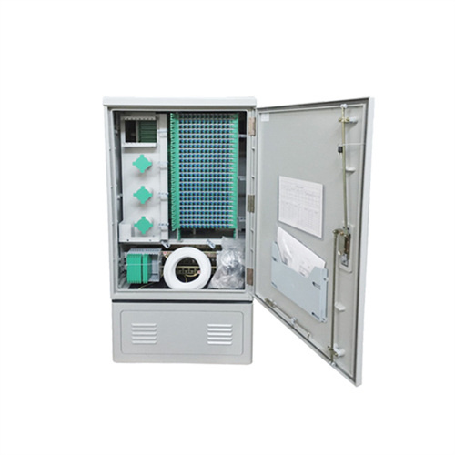
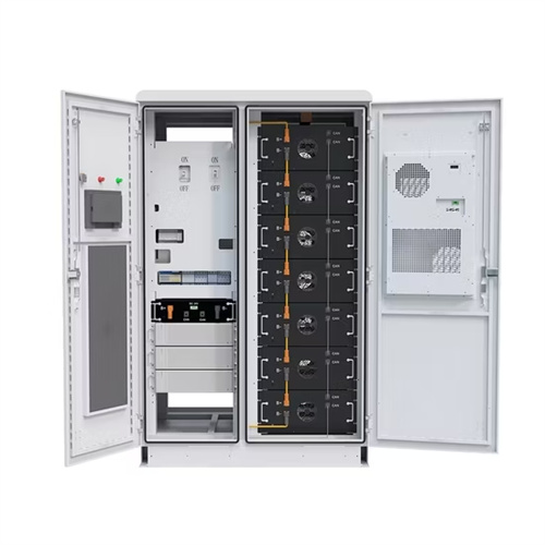
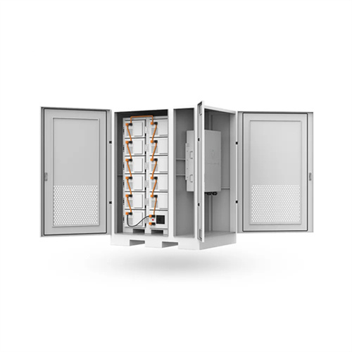
Working principle diagram of lithium battery solar container cabinet
This article will analyze the structure of the new lithium battery energy storage cabinet in detail in order to help readers better understand its working principle and application characteristics. This article will

Solar Mobile Charging Station Final Project
It provides details on the system configuration, component specifications, voltage regulator circuit design and simulation, and performance analysis of the solar
Solar Inverter and Charger Circuit for a Science Project
The following article provides an explanation of a straightforward solar inverter circuit designed specifically for beginners or school students who
Solar powered battery charger circuit
Solar power is one of the free form of renewable energy that our planet earth is blessed with. Increase in energy demands forced to seek ways for

Circuit Diagram of Mobile Phone Battery Charger Tested
Circuit Diagram of Mobile Phone Battery Charger Tested - Free download as PDF File (.pdf), Text File (.txt) or read online for free. This document describes a
Energy Storage Electrical Diagram Explanation: A Beginner''s Guide
Primary keyword: energy storage electrical diagram explanation Long-tail phrases: "battery management system wiring", "grid-tied storage schematics" Natural keyword placement (no
Portable Mobile Charger Circuit Diagram
A portable charger circuit diagram is the way to go for those who want to get technical and get the job done themselves. A diagram is essentially a
Circuit Diagram For Solar Mobile Phone Charger
The circuit diagram for a solar mobile phone charger typically includes a solar cell, an integrated voltage regulator, a series of resistors, some

Solar Battery Charger Circuit Project
A solar battery charger circuit works by converting the direct current (DC) produced by the solar panel into alternating current (AC). The AC is
12v 7ah Battery Solar Charger Circuit Diagram
When you''re looking for an efficient and cost-effective way to power off-grid solar projects, a 12V 7Ah battery solar charger circuit diagram is
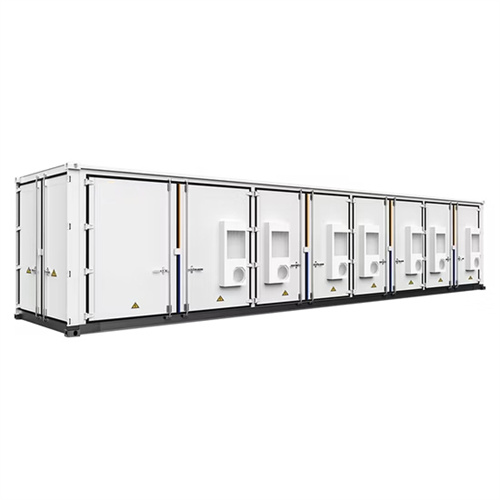
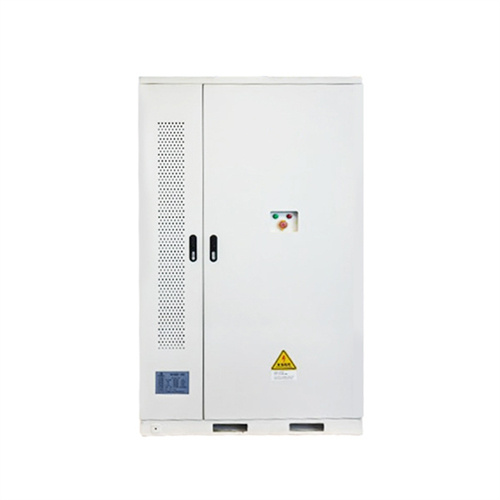
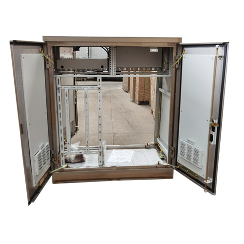
Basic circuit diagram of the supply container. It
Basic circuit diagram of the supply container. It connects solar panels, batteries and electric consumers via a locking diode, a charge controller and an AC converter.

6 FAQs about [Mobile battery solar container circuit diagram explanation]
What is solar power mobile charger circuit?
And, for this reason, we have decided that, in this tutorial, we are going to “Solar power mobile charger circuit “. A solar charger circuit is a device that generates power from sunlight. Cell phones, computers, automobile batteries, reading lamps, and personal fans all can use this power to charge their equipment.
What is a solar battery charger circuit diagram?
A circuit diagram of a solar battery charger provides a visual representation of how this device is designed and put together. It illustrates the components of the device, such as the solar cells, the rechargeable battery, and the connectors for the device, as well as the wiring and connections between them.
How a solar power mobile charger works?
1. 2. 3. 4. 5. 6. 7. The Solar power mobile charger circuit uses a solar panel with a single PN junction diode 1N4007 connected to the solar panel’s positive line to prevent reverse polarity. After the capacitor C1, a green LED is connected across the solar panel supply line to show the condition of the solar panel’s supply output.
How to charge a 12V battery with a solar panel?
Here we talk about a simple solar charger circuit. It takes power from a 20V, 1A solar panel and then charges a 12V battery. We are using a 7812 voltage regulator IC, three 1N4007 diodes, and a 2.2kΩ resistor to make sure the charging happens safely. Now let’s go step by step. First our solar panel gives us 20V DC at 1A when the sun is bright.
How to create a solar battery charger?
So, let’s dive into the world of renewable energy and learn how to create a solar battery charger! To build the solar battery charger, you must first connect the LM317 voltage regulator IC and the BC547 transistor with the help of resistors and capacitors. Then, connect the LED indicators and the voltage comparators using the LM324 quad op-amp.
How does a 6V solar battery charger work?
In the 6V solar battery charger circuit, the LM317 is set up to generate a fixed 7V output using the resistances 120 ohms and 560 ohms. The voltage comparators in the LM324 quad op-amp are used to compare the voltage levels during the charging or discharging process of the battery.
Related Contents
- Solar container inverter circuit diagram explanation video
- Schematic diagram of mobile solar container conversion circuit
- Solar container battery working principle diagram explanation
- New solar container battery explanation diagram
- Solar container principle diagram of mobile battery
- Schematic diagram of aluminum iron phosphate solar container battery
- Solar container liquid cooling system working principle diagram explanation picture
- Mobile solar container battery display picture hd
- Structure diagram of micro mobile solar container device
- Mobile lithium battery solar container power supply car brand
- Mobile solar container model video explanation
- Mobile phone battery solar container